Reaming Guide
Precision machining requires more than just good equipment — it demands attention to the details that keep your parts accurate, your tools sharp, and your production running smoothly. Whether you're reaming precision holes, maintaining tolerance-critical features, or troubleshooting tool wear, this guide brings together best practices to help you reduce downtime, cut waste, and improve overall part quality.
This page is split into the following sections:
- Choosing the Right Reamer – how to select the best tool based on material, hole type, and precision requirements
- Tolerance in Manufacturing – what it means, why it matters, and how to control it
- Reaming Best Practices – techniques and tips to get clean, accurate holes every time
- Tool Wear and Failure – how to recognize, prevent, and design around it
Use these insights to strengthen your processes, protect your tools, and consistently produce parts meet the highest standards.
How to Choose the Right Reamer for Your Application
Reamer selection depends on several factors — especially the material being machined, the type of hole, and the required finish and dimensional tolerance. Choosing the wrong type can result in poor hole quality, excessive wear, or tool failure.
Reamer Material Selection by Workpiece Material Type
Free-cutting materials (like aluminum, brass, or mild steel) allow the use of lighter reamers with less aggressive geometries. For tougher, harder, or stringy materials — such as stainless steel, titanium, or work-hardening alloys — reamers must be designed with stronger support, optimized clearance angles, and wear-resistant materials.
- Hard/tough materials: Use harder substrate, solid, or carbide-tipped reamers with heavy-duty geometry
- Abrasive materials: Consider coatings or harder substrate materials to extend tool life
- Sticky or stringy materials: Use reamers with chip-breaking flutes and high rake angles
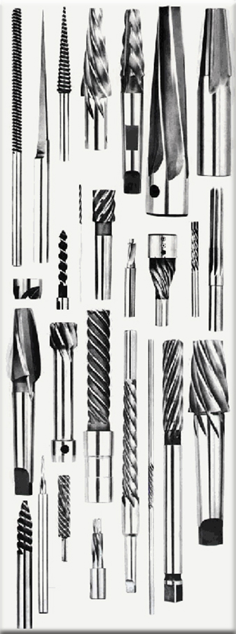
Reamer Flute Styles Explained: Left-Hand Spiral, Right-Hand Spiral & Straight
The helix direction of a reamer’s flutes does more than move chips—it influences feeding forces, wall finish, alignment, torque load, and risk of chatter or scoring. Choosing the correct flute style for your hole type and material can be the difference between a clean, size-holding bore and a scored, bell-mouthed scrap part. For a quick overview of the key differences between these styles, refer to the table below.
Left-Hand Spiral Reamers: Benefits and Best Uses for Through Holes
Use when: Reaming through holes where you want chips pushed forward and expelled out the far side—reducing the chance of recutting chips against the bore. Excellent in free-machining alloys that otherwise let a RH spiral “suck in” too fast. Also useful where parts have cross-holes or interruptions: pushing chips forward helps the tool re-engage smoothly after breaks in the cut.
A left-hand spiral (with a right-hand cut) resists self-feeding and helps keep the tool axially stable.
This provides multiple benefits:
Prevents "Sucking In" on Through Holes — In materials that cut easily (such as aluminum or brass), right-hand spiral reamers can pull themselves too aggressively into through holes, risking reamer overload, bell-mouthing, or loss of diameter control. Left-hand spiral flutes counteract this by pushing chips forward and applying slight axial resistance, allowing better control over feedrate and depth.
Reduces Tool Deflection in Long Bores or Bushings — The left-hand spiral resists natural helix pull, maintaining balanced axial feed in setups with long guide bushings or deep bores. This minimizes radial forces, keeps the reamer centered, and improves straightness and concentricity in long holes.
Better Results in Interrupted or Cross-Hole Features — In parts with intersecting cross-holes or interruptions, left-hand spirals help maintain consistent engagement and axial force, reducing the risk of chipping or misalignment and improving control where right-hand spirals might snag or shift.
Considerations: Slightly higher torque/thrust; avoid in deep blind holes (chips pack). Use generous through-coolant or external flushing to sweep chips clear of the exit face.
Right-Hand Spiral Reamers: Ideal for Blind Hole Reaming
Use when: You must clear chips from the bottom of a blind hole or from a deep cavity where chip packing will damage the cutting edges or bottom face. Good choice in ductile or “stringy” materials when coupled with chip-breaking geometry.
Behavior: The helix tends to draw the tool into the cut; feed thrust required is lower. This self-feeding characteristic is helpful in some production setups but can lead to over-advance if feed control is loose or part fixturing is compliant.
Considerations: Provide chip space and coolant; watch for chip pull-back scratching walls in through holes. Use when hole bottom must remain clean.
Straight Flute Reamers: Rigidity and Short Hole Applications
Use when: Holes are short, fixturing is rigid, or chip volume is low (e.g., light stock removal). Common in hard materials, interrupted holes, and hand or guided reaming where directional chip control is secondary to tool stiffness and guidance. Straight flutes also pair well with precision bushings and alignment fixtures in multi-station tooling.
Behavior: Maximum cross-sectional stiffness; minimal helix-induced axial thrust. This helps hold size in tough materials and reduces the tendency to wander when guided. Because chips aren’t actively lifted, coolant, air, or gravity must remove them.
Considerations: Not ideal for deep blind holes (chip packing); can chatter if misaligned or if feed is too light—use proper alignment and steady feed pressure.
Quick Selector
| Flute Style | Chip Movement* | Best For | Key Advantages | Watch For |
|---|---|---|---|---|
| Left-Hand Spiral (LH helix, RH cut) | Pushes chips forward toward hole exit | Through holes, cross-hole interruptions, free-cutting materials prone to chip welding | Chips exit ahead of the tool so they don’t get recut on the way out; reduced wall scoring; resists self-feeding for better axial control; steadier engagement through bushings & interruptions | Requires more torque/thrust; not for deep blind holes—chips pack at bottom |
| Right-Hand Spiral (RH helix, RH cut) | Pulls chips back toward the shank (up/out of hole) | Blind holes, gummy materials, vertical machines where chip extraction is critical | Excellent chip evacuation from bottoms of blind holes; tends to feed easily (“self-feeds”) reducing thrust load | Can draw into cut aggressively in free-cutting materials; chips pulled across walls in through holes may score finish if not flushed |
| Straight Flute | Minimal axial chip bias; chips tend to stay in place / follow coolant flow | Short holes, hard materials where rigidity rules, interrupted holes, manual/fixture work | Highest structural stiffness; lowest helix thrust—good for size holding & alignment in rigid setups; economical; easy to resharpen | Poor chip lifting—risk of packing in blind or deep holes; more prone to chatter if alignment isn’t solid; needs good coolant evacuation |
*Assumes conventional clockwise spindle rotation (right-hand cutting)
Understanding Hand of Cut vs. Hand of Spiral: Identification Guide
Hand of Cut describes the direction the reamer removes material. When viewed from the chamfer (cutting) end:
- If the reamer rotates counterclockwise during cutting, it is a right-hand cut reamer.
- If the reamer rotates clockwise during cutting, it is a left-hand cut reamer.
Hand of Spiral (Helix) refers to the direction of the flute’s twist, as seen from either end of the reamer:
- If the flutes twist away from you in a clockwise direction, it is a right-hand spiral.
- If the flutes twist away from you in a counterclockwise direction, it is a left-hand spiral.
Not sure which flute style is right for your part, material, and machine? Send us your print and process notes—Gammons will recommend (or design) the right reamer.
Reamer Size Selection and Tolerance Control in Precision Machining
To hold tight tolerances, reamers must resist deflection and provide consistent edge support throughout the cut. Solid reamers, particularly in smaller diameters — offer superior rigidity, resulting in better hole accuracy and repeatability.
Surface Finish vs. Hole Accuracy: Creating True Precision in Reamed Holes
A smooth surface finish does not guarantee a good hole. True hole quality includes diameter size, roundness, straightness, concentricity and repeatability. Bell-mouthing, taper, and lip height variation can all occur. Achieving both finish and dimensional precision requires:
- Proper cutting tool geometry optimized for the material
- Adequate body and flute support to reduce tool deflection
- Low runout and concentricity between spindle, holder, shank and flutes
- Consistent tool holding with minimal radial movement
Many end users are not equipped to evaluate these factors reliably. Tenths-reading micrometers are often used improperly—operators may unknowingly measure on relieved margins or tilt the tool, leading to false readings. Furthermore, most shops do not have concentricity or roundness testers to assess concentricity or flute lip height variation, both of which affect tool performance.
For example, some manufacturers grind shanks using centerless methods and then grind the flutes between centers, resulting in misalignment between the cutting edges and shank axis. This causes eccentric loading during reaming, which contributes to premature wear and inconsistent hole geometry. At Gammons, we grind the entire tool between centers to ensure axial alignment of shank, body, and cutting edges—critical for concentricity and true positioning in precision bores as well as surface finish and tool life.
Reamer Cost Analysis: Long-Term Value and Salvage Considerations
Lower-cost tools may appear economical up front but often result in higher long-term costs due to inconsistent performance, more frequent replacements, and scrap or rework. Reamer selection should factor in material type and machining environment.
Tapered reamers are an excellent long-term value and can often be reground multiple times while maintaining concentricity and geometry. By contrast, salvaging a worn straight solid reamer may require reducing the diameter, which may not be compatible with the original hole specification.
Additional Factors in Reamer Selection: Materials, Machine Condition & Coolant
- Reamer material: High-speed steel for general use; carbide for wear resistance; coatings for improved lubricity
- Spindle and machine condition: Poor alignment may require floating holders or piloted reamers
- Coolant use: Critical for chip removal and tool life in most reaming operations
Precision reaming demands more than a sharp tool—it requires a well-controlled process. Alignment, tool holding, spindle and machine condition, coolant use for chip removal and tool life and material variability all influence the result. Even the best reamer cannot compensate for a poor setup.
At Gammons, we design reamers not just to cut—but to perform consistently, under real-world conditions. Our tools are ground for concentricity, roundness, and repeatability—so you can produce reliable results – consistently and confidently.
Need help selecting or inspecting reamers for your application? Contact Gammons. We're here to help you get it right.
Tolerance Standards in Manufacturing: Specifications and Control
Tolerance in manufacturing refers to the permissible variation in a physical dimension—the allowable range within which a machined part can deviate from its specified size while still functioning correctly.
Tolerances define how close to “ideal” a dimension must be, ensuring consistency, interchangeability, and reliable performance across components.
Consider aerospace structural components, such as those used in aircraft fuselages. These parts require precisely reamed holes for fasteners that join critical sections of the airframe. If the hole diameters fall outside their specified tolerances—whether slightly oversized or undersized—fasteners may fit too tightly or too loosely. These deviations can compromise structural integrity, increase fatigue risk, and result in failed inspections or costly rework.
In aerospace applications, even minor tolerance violations can jeopardize part fitment, safety, and regulatory compliance.
An oversized hole may cause a fastener to loosen in service; an undersized one may prevent full insertion. Both scenarios threaten airworthiness.
Improper tolerance control can lead to:
- Poor component fit and alignment
- Increased mechanical wear and vibration
- Reduced product reliability and service life
At Gammons, we understand these challenges and engineer our reamers to extremely tight tolerances, ensuring your manufacturing processes consistently produce precise, reliable components and avoid these costly issues.
Tolerance Notation and Specification Formats
Tolerances are commonly expressed as plus/minus values next to a nominal dimension. For example, using our aerospace example:
Diameter: 0.2756 in
Tolerance: ±0.0002 in
Acceptable range: 0.2758 in to 0.2754 in
This tolerance ensures that fastener holes will reliably accommodate the specified hardware, even with minor machining variations.
Types of Tolerances: Limit, Unilateral & Bilateral Methods
The type of tolerance you select should align with your application’s specific requirements:
Limit Tolerances: Maximum and Minimum Dimension Boundaries
Clearly defines maximum and minimum allowable dimensions. Any measurement within these limits is acceptable, ensuring clear dimensional boundaries.
Unilateral Tolerances: Single-Direction Allowable Variation
Allows deviation in only one direction (positive or negative). For instance, a critical shaft diameter may be specified as +0.0002 / -0.0000 in to prevent undersizing.
Bilateral Tolerances: Positive and Negative Allowable Deviation
Permits deviation above and below the nominal dimension:
- Bilateral Equal: Equal tolerance in both directions (e.g., ±0.0002 in).
- Bilateral Unequal: Different tolerances in each direction (e.g., +0.0002 / -0.0004 in), useful in applications needing specific fitting characteristics.
Importance of Tolerance Control in Manufacturing Quality and Safety
Precise tolerance control impacts all industries—from automotive to aerospace and medical devices. In aerospace applications, improper hole tolerances can lead to structural failures, increased maintenance cycles, and noncompliance with strict industry standards. Tight tolerance control ensures safe, reliable, and efficient performance—whether in flight-critical components, medical devices, or precision tooling.
Below are Gammons standard tolerances for straight (non-tapered) reamer schedules:
Up to ½" +.0002/-0
Over ½" to 1 ½" +.0003/-0
Over 1 ½" +.0004/-0
For the most precise results, always double-check your measurements and tolerances before proceeding. To make the process easier, be sure to try our Reamer Sizing Calculator, a helpful tool designed to quickly determine the correct sizing and reduce guesswork during planning.
Gammons is committed to manufacturing precision reamers, allowing your business to consistently meet quality standards, minimize production issues, and maintain excellent reliability and performance.
Professional Reaming Best Practices for Superior Hole Quality
Reaming is one of the most precise operations in machining — but achieving accurate, clean holes requires careful attention to setup, feed, alignment, and tool condition. Below are speed and feed rates, key precautions and tips to avoid reamer failure, poor finish, or dimensional inaccuracies.
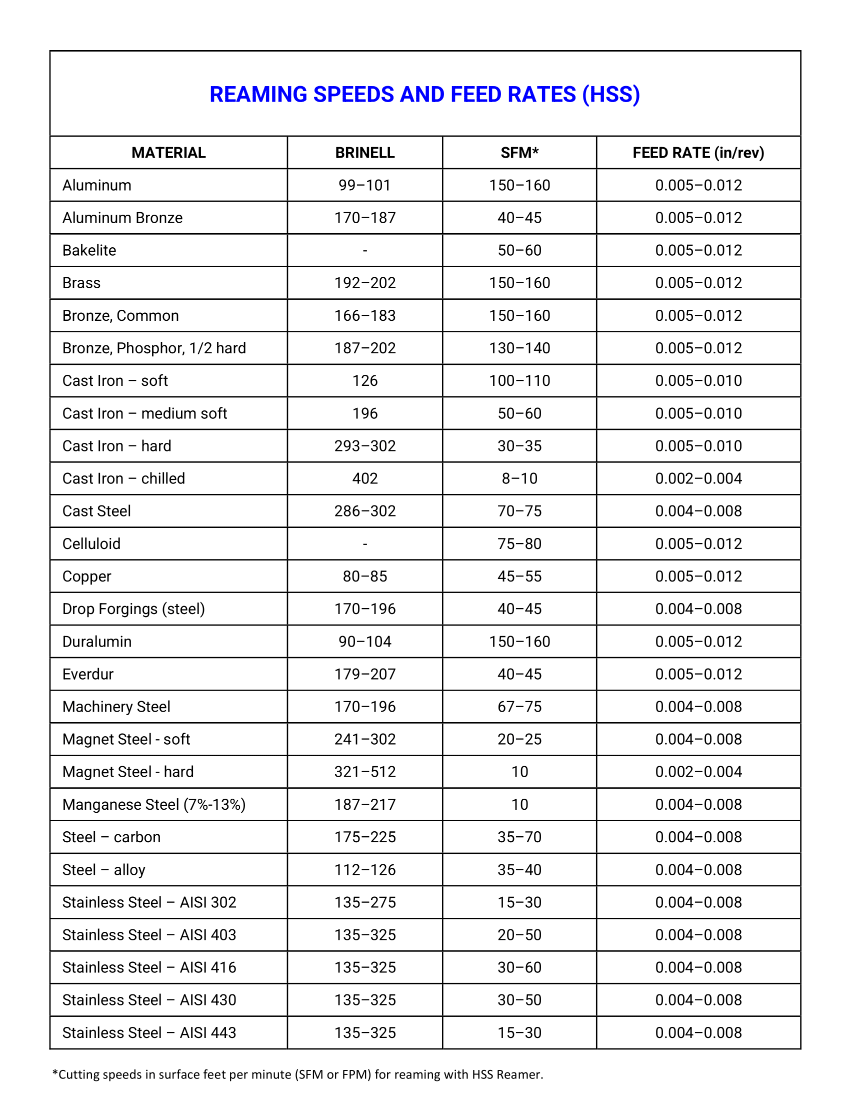
Optimal Reaming Feeds and Speeds for Straight Holes Using HSS Reamers
As a general rule, straight hole reaming should be done at about two-thirds the speed used for drilling the same material. However, feed rates for reaming are often much higher — 200% to 300% of drill feeds. The amount of feed may vary with different materials, but a good starting point would be between .0015" and .004" per revolution. Too low a feed may “glaze” the hole, which has the result of work hardening the material, causing occasional chatter and excessive wear on the reamer. Too high a feed tends to reduce the accuracy of the hole and the quality of the surface finish.
Too low a feed rate can cause the reamer to rub or burnish instead of cutting, accelerating wear and leading to undersized or poor-quality holes.
The most efficient cutting speed depends on several factors, including the material being reamed, amount of stock left in the hole, tool material (HSS or carbide), finish requirements, and overall setup rigidity. A good starting point is typically one-third to one-half the speed used for drilling.
When using carbide reamers, speeds can often be increased over those recommended for HSS — but only when the setup is rigid. Carbide tools are less tolerant of vibration, and even brief chatter at the start of a cut can chip the cutting edges. This is especially important in reaming, where overhang and limited cross-section reduce rigidity compared to turning operations.
Close tolerances or fine surface finishes often require running at slower speeds than standard recommendations. In all cases, chatter must be avoided — it shortens tool life and compromises hole quality. Always select a speed that is low enough to eliminate vibration entirely.
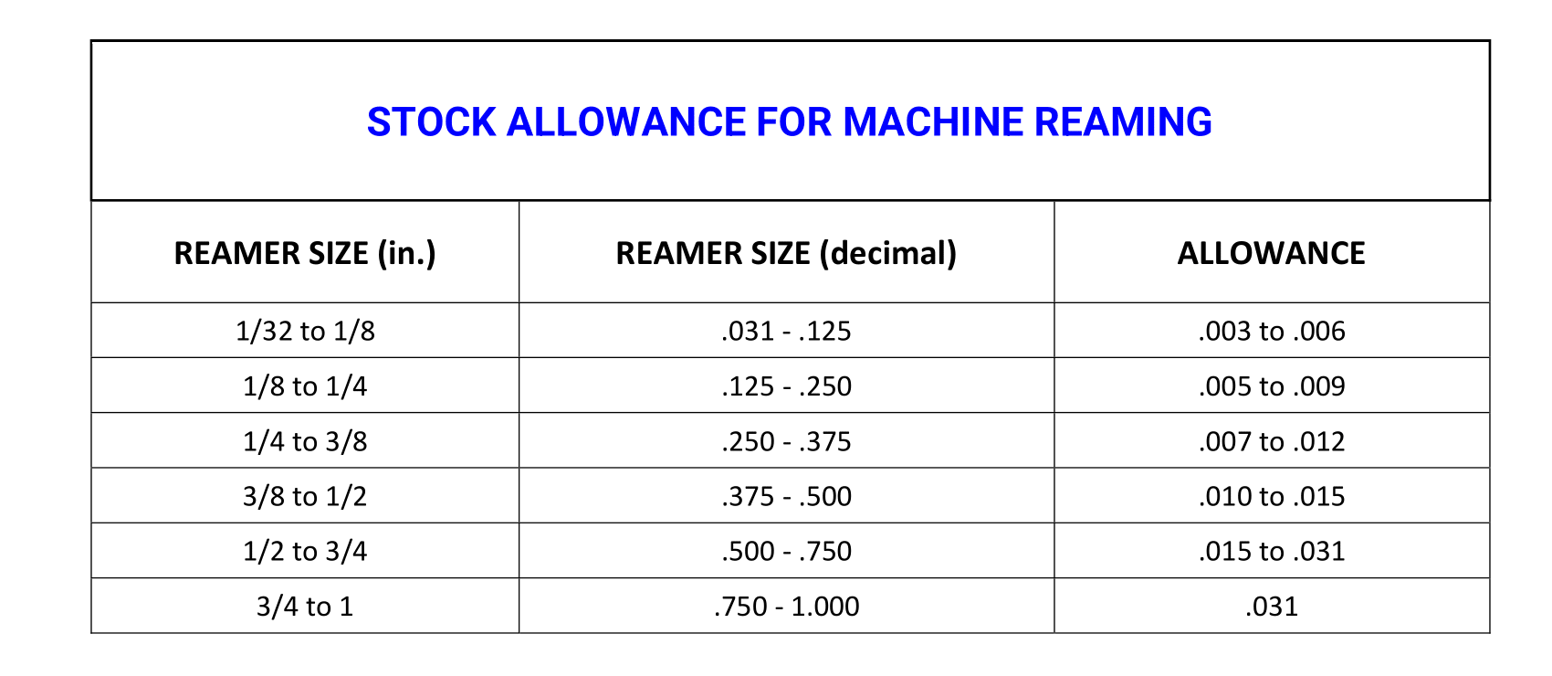
Stock Allowance in Reaming: Optimal Material Removal for Precision
As a general rule, stock removal for reaming should be approximately 3% of the hole diameter. To cut cleanly, reamers need enough material left from the prior operation. Too little stock can cause the tool to burnish rather than cut, while too much can overload and deflect the tool.
The usual practice is to ream from 0.004" to 0.012" on diameter (e.g. 0.002" to 0.006" on a side) in finishing operations. Except in large diameters, seldom does one ream over 0.015". As drill sizes vary in increments of 1/64", it is found that theoretically 1/64" has been left for reaming, but in fact it is only 0.012", as most drills cut oversize by 0.002" to 0.004".
In smaller sizes, especially those below ½", it's advisable to ream only 0.006" or 0.008" in diameter. This is relatively easy to arrange, as drill sizes come in smaller increments within this range.
- Machine reaming: 0.010" for 1/4" holes, 0.015" for 1/2", up to 0.025" for 1.5" holes
- Hand reaming: 0.001" to 0.003" stock allowance is typical
Design Considerations for Reaming: Optimizing Part Features for Tool Performance
Good product design can make reaming more effective and reduce tool wear. Whenever possible, allow the reamer to pass completely through the part — this avoids the challenges of reaming blind holes, which can cause chip buildup and increase the risk of tool damage.
If blind holes are required, control depth carefully and avoid bottoming out the tool. For clean, accurate entry, the reamer should approach the workpiece surface at a perfect right angle. Angled starts can prevent full tooth engagement, leading to poor finish and misalignment.
Manual Hand Reaming Techniques for Precision Machining
Hand reaming is best suited for rigid workpieces and low-volume precision tasks. A double-end tap wrench should always be used to rotate the reamer — it provides balanced torque and helps maintain alignment. Single-end wrenches can introduce side force, leading to misalignment or poor hole quality.
Rotate the reamer slowly and steadily, allowing it to self-align with the hole. Wrenches should offer enough leverage for smooth, controlled torque to reduce vibration and chatter. Hand-feed rates are typically higher than machine reaming — feeds up to 25% of the reamer’s diameter per revolution are common.
For small, light parts, it’s often better to clamp the reamer vertically in a vise and lower the workpiece onto it by hand. If the part lacks enough mass to dampen vibration, use a holding fixture with dual handles to improve control and add weight.
In production settings, horizontal reaming machines are often used. These mount the reamer on a slow-speed, motor-driven shaft. Operators feed the part slowly over the rotating reamer to ensure alignment and consistent finish.
No matter the method, reamers should never be rotated in reverse to exit the hole. Doing so dulls the cutting edges. If possible, continue forward rotation and push the reamer through the hole. If reversing direction is unavoidable, maintain forward rotation while withdrawing.
CNC Reaming Cycles: Selecting the Right G-Code for Finish Quality
For CNC reaming, choose a canned cycle that keeps the tool moving smoothly and continuously. A feed-out retract generally produces the best finish and helps avoid bore witness marks.
- Prefer a feed-out cycle for best finish: Use
G85(feed in, feed out at the programmed feed). Rapid retract can leave witness marks in the bore. - Avoid rapid-out cycles when finish matters:
G81(feed in, rapid out) may leave marks, especially in tighter or longer bores. - Be cautious with spindle-stop retract cycles:
G86stops the spindle at depth, then rapids out. That stop/restart behavior can mark the wall and is generally not preferred for finish reaming. - Do not peck ream: Avoid drilling-style pecking or cycle interruptions. Use a smooth, continuous feed whenever possible.
- Never reverse the spindle to exit: If you must withdraw before full depth, keep the spindle rotating in the cutting direction while retracting.
Note: Canned cycle behavior can vary by control. Always verify the cycle definition in your machine/control manual before running.
Spindle and Tool Alignment: Critical for Precision Hole Quality
Accurate reaming depends on perfect alignment between the spindle, tool, bushing, and hole. Misalignment can cause tapered, oversized, or bell-mouthed holes and significantly reduce tool life.
To maintain alignment:
- Use floating or adjustable tool holders
- Ensure rigid and concentric setups
- Apply additional back taper to the reamer
Plain reaming will not correct axis misalignment across a hole series. For concentricity, use line reaming with progressively sized holes and a guided reamer bar supported at both ends.
Reamer Holding Methods: Collets, Chucks & Quick-Change Systems
A common means for holding and driving reamers arr collets or the three-jaw chuck. Another is the straight-sleeve and setscrew method. End mill holders with set screws should be used with care as the set screw will introduce side pressure. Taper shanks are sometimes used with a sleeve or socket. Reamers with adapters for quick-change chucks are used on production set-ups.
Floating Tool Holders: Compensating for Spindle Misalignment
For lightweight fixtures, use a rigid drive and allow the fixture to float. For heavier setups, floating holders are essential to permit the tool to self-align during reaming. In turning centers and turret lathes, rigid holders can lead to bell-mouthed holes — floating holders provide full compensation for angular and parallel misalignment.
Effective floating holders allow:
- Angular movement to adjust tool tilt
- Parallel offset to absorb lateral misalignment
Floating holders help compensate for many problems of misalignment by allowing angular or lateral movement, but not all floating holders are equally rigid. Some correct only for angular misalignment, others for parallel offset, and a few allow both. The best designs maintain movement in only the necessary directions while restricting all others for stability.
However, floating holders aren’t always enough. In some machines, like turret lathes with worn slides, a floating holder may still allow pressure to build unevenly. In these cases, adding a slight back taper to the reamer may be necessary. But excessive back taper — especially more than .005" per inch — will reduce tool life and may compromise tolerances. Start with the minimum amount needed to achieve the desired result.
The best floating holders combine both types of compensation and should be tuned to handle the maximum misalignment expected on a given job. When reamers must guide themselves into previously made holes, they require floating holders to maintain alignment and prevent tapered, out-of-round, and bellmouth holes. There are several types of floating holders, some of which permit an angular float; others permit a parallel float; still others permit both features.
Correcting Out-of-Round Holes: Techniques and Tool Modifications
To straighten holes that have drifted from centerline, consider modifying a standard reamer into an end-cutting reamer by grinding the chamfer flat. This allows the tool to cut like an end mill. Use with careful guidance and support for accurate correction.
Floating holders are especially helpful with stainless to reduce work hardening and compensate for misalignment. If your tools are wearing out faster than expected, the cause is often a combination of small setup factors. We design around real-world machine limitations, not lab-perfect conditions. Understanding these root causes helps prevent failures — not just fix them. Gammons tools are built with these factors in mind to deliver longer life, better results, and fewer surprises.
Piloted Reamers and Guide Bushings: Precision Control Methods
Guiding the reamer with bushings improves accuracy and reduces tool wear. Ideal setups include a fixed jig and bushing with minimal overhang. Accurate spindle alignment is especially important to avoid reamer damage from contacting hardened bushings.
When reaming without a jig, add a pilot or taper to the reamer’s front to aid alignment.
Avoid using the reamer to “drag” the part into alignment. This practice often results in excessive wear, chipped edges, or tapered holes. The reamer should never be used to locate the part — that job belongs to properly aligned jigs and bushings.
In production, bronze or fiber caps are sometimes placed over hardened bushings to act as soft leads and reduce initial impact. However, these do not protect the tool if the reamer is not perfectly centered — proper spindle alignment is still essential.
When locating holes precisely from a fixed point or another feature, the most reliable method is to use a jig or fixture with bushings placed in exact relation to locating surfaces. These guide the reamer accurately and reduce the risk of misalignment.
For long holes, guide the reamer on both sides of the work using a piloted tool. Guide bushings should fit snugly on the pilot (but not so tightly they bind). Pilots may be grooved along their length to allow coolant flow and to evacuate chips that could otherwise wedge between the bushing and pilot.
For short holes, a single guide bushing at the hole entrance may suffice. In this case, the bushing can be sized to fit the reamer flute diameter.
When reamers are guided by bushings, a rigid drive (where the reamer is held directly in the spindle) is acceptable — as the bushing maintains alignment. But if the reamer must align itself into a hole without bushing guidance, a floating holder is essential to prevent bell-mouthing and tool wear caused by misalignment.
Reaming in Lathes and Turning Centers: Setup and Troubleshooting
In turning operations, the work rotates while the reamer remains stationary — opposite of typical milling or drill press setups. In practice, misalignment is common and can result in bell-mouthed or oversized holes.
Misalignment typically falls into two categories:
- The reamer is parallel to the spindle but offset vertically or laterally
- The reamer is angled relative to the spindle
Common causes of misalignment include:
- Worn ways or slides on the machine
- Worn or dirty tool holder bores
- Worn sleeves or bushings
- Improper machine leveling
- Misaligned or loose tool slides
- Errors in turret indexing or positioning
These can be remedied by:
- Cleaning or reboring holders
- Using adjustable or floating holders
- Adding additional back taper to the reamer
Back taper can reduce rubbing and bell-mouthing but may shorten tool life in close-tolerance applications. Use minimal taper necessary to achieve the desired result.
Reaming Tapered Holes: Heavy-Duty Techniques for Complex Geometries
Reaming tapered holes involves heavy stock removal and full tool engagement — increasing torsional stress and risk of chatter. Larger tapers worsen these effects. Tapered reamers must be built strong, with large flutes and well-supported cutting edges.
Because tapered reamers are not end-cutting tools, the pre-existing hole must be larger than the small end of the reamer so the tool can enter and begin cutting along the taper.
For best results:
- Use a roughing taper reamer followed by a finishing reamer
- Roughers should have fewer flutes and include chip breakers
- Finishers should have a different flute count and spiral design than the rougher
For machine reaming, high-spiral reamers (around 45°) with 2–5 flutes work well. Use a spiral direction opposite the spindle rotation to aid chip control. This usually means a left-hand spiral as left-hand cutting tools are exceedingly rare. Avoid high-spiral tools for blind holes, as they tend to pack chips rather than eject them.
To combat chatter or out-of-round holes, try reamers with uneven flute spacing and non-opposing cutting edges. Duplex flutes are excellent for this. These are harder to measure but may be necessary in problematic setups. Avoid straight flutes if possible.
For hand reaming of tapered holes, use reamers with a 10° spiral opposite the cut direction for better control and finish.
Eliminating Reamer Chatter: Vibration Control and Setup Optimization
Chatter during reaming reduces tool life and leaves poor surface finish. It can stem from excessive speed, insufficient feed, poor machine rigidity, or tool overhang.
Common causes:
- Too much clearance on the reamer
- Weak fixturing or holding of the workpiece
- Overhang of the spindle or tool
- Looseness in floating holders
- Use of straight flute reamers
Correcting these issues — even small ones — can dramatically improve hole quality and tool longevity.
When working with aluminum, tool selection is especially important. Helical fluting works best for straight holes, while spiral flutes are preferred for tapered holes. Duplex taper reamers also perform exceptionally well on precision aluminum work. Be sure to leave enough stock in the hole for the reamer to cut effectively—if not, the tool may only burnish the surface rather than remove material.
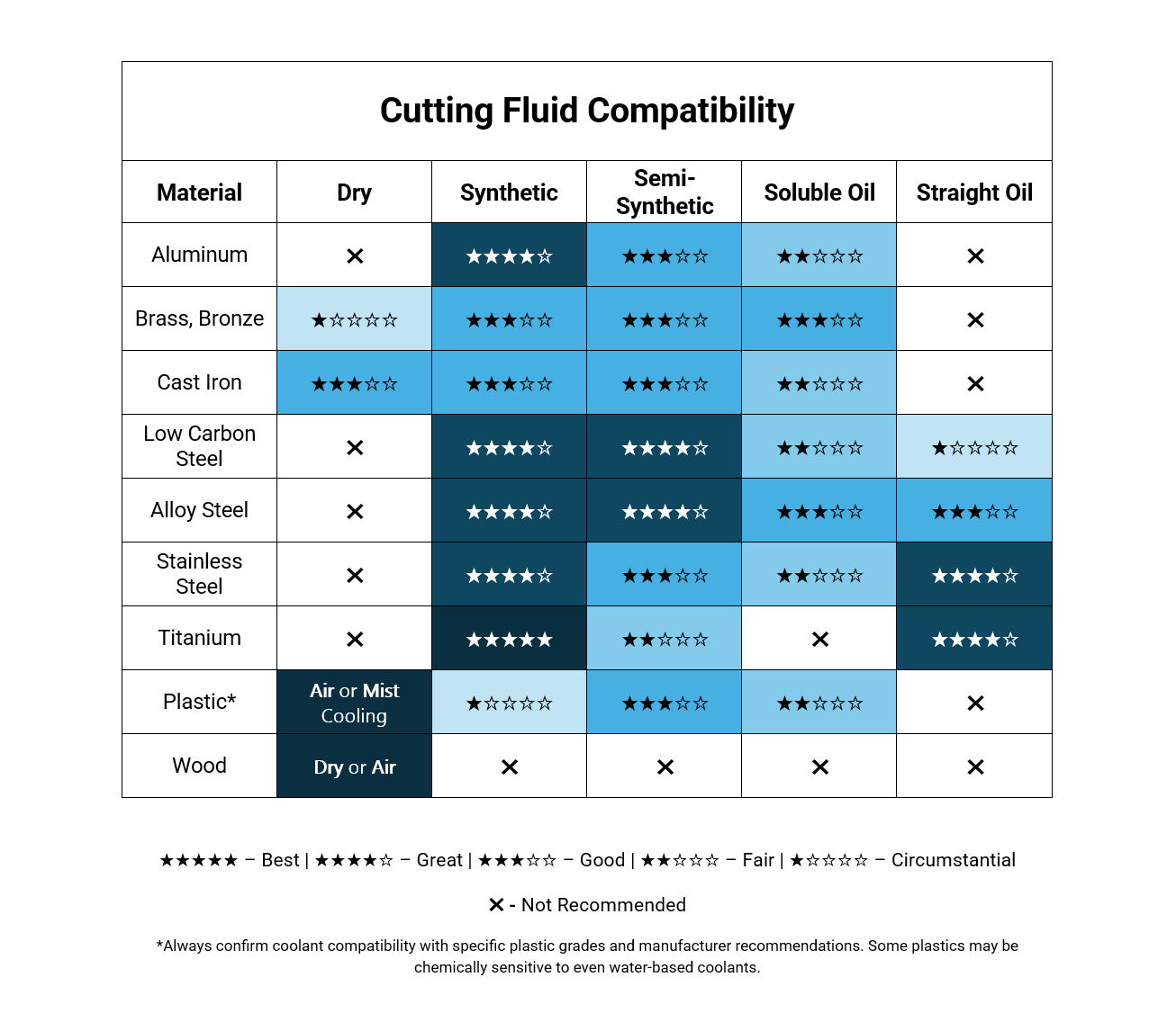
Cutting Fluid Selection for Reaming: Optimizing Chip Evacuation and Finish
In reaming, the primary function of coolant is to improve surface finish, not necessarily to reduce heat. Choose lubricants that aid cutting action and flushing of chips from the hole. Below are our recomendations for cutting fluids for each common material.
Reamer Regrinding and Maintenance: Extending Tool Life Through Proper Sharpening
To get the best life from a reamer, don’t wait until it stops cutting. Regrind the reamer before major dulling occurs. For straight reamers, only the chamfer should typically be resharpened, as size is usually critical.
Use a cutter grinder to ensure uniformity across flutes. Avoid hand sharpening — uneven flutes can cause oversize holes or poor finishes. Return to Gammons to ensure proper cutting geometry.
End Milling vs. Reaming: Speed, Feed & Tool Selection Differences
End mills are versatile tools used to cut a wide range of materials. To achieve the best results and avoid premature wear, proper cutting speed and feed selection are critical.
Before selecting a cutting speed, it's essential to know the material type and hardness. Harder materials require slower speeds. Likewise, some materials — especially those alloyed with nickel, chromium, cobalt, or molybdenum — demand lower speeds due to their resistance to cutting, even if they're not especially hard.
If you’re unfamiliar with the material, start with the lowest recommended speed for that class and gradually increase until optimal performance is reached. The broad speed ranges accommodate machine limits and setup variables.
For longer tool life, use the lower end of the cutting speed range with a generous feed per tooth — as long as tool diameter, length, and setup allow. If machine spindle speeds are limited, it's better to run below the suggested range than exceed it.
Watch for heat discoloration on chips or the tool — this signals excessive speed and can lead to premature failure. If edges dull quickly without discoloration, the material may be highly abrasive or resistant to chip separation; in this case, reduce the cutting speed.
Consistent feed control is also key. Erratic hand feeding causes uneven tooth loading, which can chip corners or snap the tool at the shank. A controlled power feed is strongly recommended.
Climb milling — when appropriate — allows for faster speeds and extends tool life by reducing tool pressure and heat. Using multi-flute end mills increases production rates by allowing higher overall feedrates through additional cutting edges.
Tool Wear and Reamer Failure: Causes, Prevention & Solutions
Tool wear is a normal part of machining — but how fast it happens, and how it impacts performance, depends on the tool’s design and setup. Short tool life, chipped edges, chatter, and poor finish often trace back to poor rigidity, mismatched materials, or overloading.
At Gammons, we design precision tools that last longer, cut cleaner, and reduce wear — even in tough materials or unstable conditions. Our engineers bring decades of experience developing high-performance reaming tools for demanding operations.
Common Causes of Reamer Wear and Tool Failure
Most tool failures stem from five common issues. Here’s what to watch for:
Structural Rigidity Issues and Deflection
Rigidity is critical for dimensional accuracy, surface finish, and tool life. Deflection from loose fits, vibration, or long overhangs can quickly wear a cutting edge or ruin a part.
Harder or work-hardening materials demand solid reamers. Chamfer relief, rake angles, and proper clearance must match material hardness — and for high Brinell values, carbide tips may be required.
Excessive Cutting Forces and Tool Overload
Overloading occurs when aggressive feeds, tough materials, or poor machine condition push a tool beyond its design. Even precision reamers fail when feed pressure exceeds their structural or chip-disposal limits.
Work-hardening materials (like stainless steel) require helical flutes, narrow lands, and optimized clearance angles to prevent excessive load and premature failure.
Poor Chip Evacuation: Buildup and Recutting Issues
Trapped or recut chips cause edge breakdown, overheating, and failure — especially in blind holes or with ductile materials. Chip welding is a common issue with soft steels, copper alloys, and titanium.
Chip breakers and rake geometry are essential to prevent clogging and promote smooth flow.
Vibration and Chatter: Edge Damage and Surface Problems
Chatter leaves visible marks and leads to edge wear or breakage. It's often caused by flexible setups, backlash, or long tool extensions.
Spindle Misalignment and Inconsistent Feed Rates
Shock loading from poor alignment or inconsistent feed can chip cutting edges and shorten tool life. Torsional vibration, backlash, and “stick-slip” motion can worsen the problem.
Decades of application experience means Gammons can help you select the right tool and setup for your job—so you get reliable results, less downtime, and longer tool life.
Hidden Causes of Reamer Failure: Storage, Handling & Maintenance Oversights
Beyond feed rates and tool wear, reamer performance can also suffer due to often-overlooked setup and handling issues. Here are several failure causes not always caught during troubleshooting:
- Dirt, rust, or burrs in the spindle or tool holder can introduce misalignment or slippage.
- No lubrication between the guide bushing and reamer can lead to binding, friction, or premature wear.
- Improper sharpening techniques such as uneven relief, grinding cracks, or coarse end-grinds can overload flutes or cause chatter.
- Bent reamer shanks(often caused by improper handling or crashes) lead to oversized or tapered holes.
- Worn or loose spindle bearings can allow tool runout, resulting in bell-mouthed or rough holes.
- Material build-up on cutting edges (especially in mild steel or aluminum) can cause reamers to gradually cut oversize. Switching to a better coolant or a reamer with polished or treated surfaces may help.
Proper Reamer Storage and Handling Procedures for Longevity
Even the best reamers can fail prematurely if they're mishandled or improperly stored. Careful handling and proper storage practices are essential to preserve cutting edges and ensure consistent performance on the shop floor.
Reamer Binding: Clearance and Geometry Mismatches
Binding can occur when clearance and rake angles are not properly matched to the application. Reamers with wide lands or insufficient back-off angle are especially prone to rubbing or jamming inside the hole. Check manufacturer specs to ensure the geometry is within limits for your material and setup.
Flute Damage: Nicks, Rust Pits & Edge Protection
Flute damage often comes from improper handling or storage — not just from cutting. Even a minor nick or rust pit on a cutting edge can compromise reamer performance. Always store reamers in separated racks or boxes to protect the edges, and coat them lightly with oil when not in use. Treat them with the same care the manufacturer does when returning them from sharpening.
Feed Rate Inconsistency and Torsional Vibration Problems
One of the most common causes of overload is a sudden change in feed rate — either from operator input or from internal machine behavior. Excessive feed beyond a tool’s chip-carrying capacity can cause chipped edges or total failure, especially in carbide tooling.
Structural deflection is a hidden culprit. For example, as a drill breaks through a workpiece, the machine's structural components may spring back toward their unstressed shape. This can drive the cutting edges deeper into the work, causing a sudden bite and tool breakage.
Backlash in gearing or leadscrew mechanisms can introduce inconsistent feed. Hydraulic or air-powered systems may compress slightly before delivering motion, creating elastic lag that leads to jumpy feed once released.
Even with lubrication, machines operating at slow feed speeds may experience "stick-slip" motion — where the cutter rubs and builds pressure, then suddenly digs in and surges forward. This results in jerky motion and uneven chip loads on the cutting teeth.
Torsional vibration is especially dangerous in rotary drive systems. If rotation becomes erratic and momentarily stops, cutting teeth can shatter when re-engaged with the work. A few damaged teeth can snowball into full tool failure as remaining teeth are forced to absorb more load than they were designed for.